
The transformer winding resistance test procedure is a critical DC diagnostic test that evaluates the condition of transformer windings, tap changer contacts, and bushing connections, Per IEEE C57.152, phase-to-phase resistance variation must not exceed 1% – and field measurements must fall within 5% of the original factory test value after temperature correction.
What is transformer winding resistance test?
Understanding what is what is winding resistance test of transformer starts with the purpose: it measures the DC resistance of each winding to detect loose connections, broken conductor strands, open circuits, and faulty tap changer contacts, The transformer winding resistance test is performed at commissioning, after every major fault, after tap changer maintenance, and on a defined preventive maintenance schedule.
What faults does it detect?
The test identifies the following defect types before they cause catastrophic failure:
- Loose or corroded connections: Elevated resistance at bushing terminals or winding leads – indicates contact degradation
- Broken conductor strands: Partial open circuits in multi-strand windings increase resistance asymmetrically between phases
- Short-circuited turns: Reduces resistance below factory value – indicates intra-winding insulation failure
- Tap changer contact resistance: High contact resistance at any tap position indicates contact erosion, contamination, or misalignment – a common cause of transformer overheating
Read More : How to Find Transformer Rating ?
Importance of winding resistance measurements for transformer diagnostics
The measurement of winding resistance is one of the most cost-effective transformer diagnostic tools – requires only a DC test set and delivers results no other test can provide. The transformer winding resistance test procedure supports four critical diagnostic applications:
- Commissioning verification: Confirms factory values are maintained after transport and installation – detects damage from transit vibration or improper handling
- Condition assessment: Trending resistance values over multiple cycles identifies gradual degradation before failure – enabling planned maintenance instead of emergency replacement
- Post-fault evaluation: After through-fault events, the transformer winding resistance test procedure confirms whether mechanical damage or strand breakage occurred – a pass/fail decision before re-energization
- Tap changer diagnosis: Applied at every tap position, reveals contact erosion – the leading cause of OLTC-related transformer failures globally
Read More : Protection of Transformer in Power System :A Complete Guide
transformer winding resistance test procedure
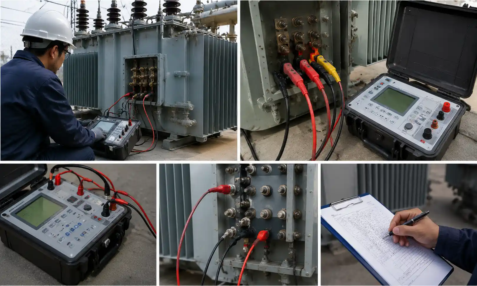
The complete transformer winding resistance test procedure for measurement of winding resistance of transformer windings follows these steps per IEEE C57.152 and IEC 60076-1:
- De-energize and ground: All windings de-energized and grounded – test leads must never be connected to an energized transformer
- Stabilize oil temperature: Wait 3–8 hours until top-bottom oil temperature difference is less than 5°C – this is the correction reference temperature
- Connect test equipment: Micro-ohmmeter or DC resistance bridge – Kelvin (4-wire) connections mandatory to eliminate lead resistance
- Apply test current: Minimum 1% of rated winding current; maximum 15% per IEEE C57.152 – prevents winding heating during test
- Wait for stabilization: Do not record readings until current is fully stable – typically 1–5 minutes for distribution transformers
- Record all readings: All three phases at same tap position; record oil and winding temperature at time of measurement
- Apply temperature correction: R₇₅ = Rₜ × (235 + 75) / (235 + t) for copper windings – correct all readings to 75°C reference
- Discharge the winding: Short-circuit through a resistor before disconnecting leads – prevents dangerous voltage spikes from stored magnetic energy
Read More : Top Power Distribution Transformer Manufacturers | Chkhele
Factors causing transformer winding resistance variations and damage
Understanding what causes abnormal results in the winding resistance test transformer diagnostics helps interpret test data correctly:
- Temperature: Resistance varies linearly with temperature – all readings must be corrected to the same reference temperature (75°C for copper) before comparison
- Winding inductance: Large power transformers have very high inductance – current takes much longer to stabilize than in small distribution units; premature readings produce false high resistance values
- Tap changer position: Resistance changes at each tap position – measurements must always be taken at the same tap position for valid historical comparison
- Core remanence: Residual magnetism in the core from previous testing or switching can affect stabilization time – degaussing may be required before accurate measurement on some designs
- Lead resistance: Test lead resistance contaminates 2-wire measurements – Kelvin (4-wire) connections are mandatory for accurate low-resistance winding measurements
Find Our Transformers Range : Distribution Transformers
Best practices for maintaining accuracy in field resistance measurements
Accurate measurement of winding resistance of transformer windings in field conditions requires strict adherence to the following best practices:
| Best Practice | Requirement |
| Temperature stabilization | Wait until top-bottom oil temperature difference <5°C – minimum 3 hours after de-energization |
| Kelvin (4-wire) connections | Mandatory for all winding resistance measurements – eliminates lead and contact resistance |
| Test current limit | Maximum 15% of rated winding current per IEEE C57.152 – prevents heating during test |
| Current stabilization | Record readings only after current is fully stable – verify on instrument display |
| Winding discharge | Always short-circuit winding through resistor after test – prevents voltage spike injury |
| Temperature recording | Record oil and ambient temperature at time of every measurement – required for correction |
| Tap position documentation | Record exact tap position for every measurement – comparison only valid at same position |
challenges during transformer winding resistance test procedure
Field application of the transformer winding resistance test procedure presents specific technical challenges, Compliance with winding resistance test of transformer standard requirements minimizes these risks:
- Long stabilization times: Transformers above 100 MVA may require 30+ minutes – boost voltage (preferred over higher current) to accelerate saturation without exceeding 15% current limit
- Induced voltage hazard: Inductive energy creates dangerous voltage spikes on disconnection – always discharge through resistor first
- Thermal drift: Winding temperature may drift during long tests – record temperature at start and end; flag tests with >2°C change
- OLTC contact variability: Must be tested at every tap position – winding resistance test of transformer standard requires each tap within 5% of factory values
Contact Chkhele to get the best transformer
Chkhele manufactures transformers with factory-conducted transformer winding resistance test and full routine test documentation – giving commissioning engineers baseline data for accurate measurement of winding resistance comparison throughout service life.
Every Chkhele transformer is delivered with complete what is winding resistance test of transformer baseline data and a winding resistance test transformer report per IEC 60076-1 and IEEE C57.12.90 – enabling direct factory-to-field comparison at any point in service life.
For inquiries or technical support, contact Chkhele directly or visit the full product range on the Chkhele website.
FAQs
Why Should Winding Resistance Be Tested?
Winding resistance testing detects loose connections, broken strands, and faulty tap changer contacts before they cause overheating or failure – enabling planned maintenance and preventing unplanned outages.
How often should transformer windings be tested?
Per IEEE C57.152, winding resistance should be tested at commissioning, after every major fault or through-fault event, after tap changer maintenance, and at least every 3–5 years as part of routine condition assessment.
Why is temperature correction so important in this procedure?
Winding resistance varies with temperature, Per IEC 60076-1, all measurements must be corrected to the 75°C reference temperature before comparison with factory values – uncorrected comparisons produce false pass or fail results.
