

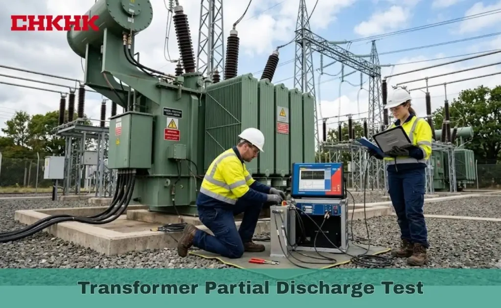
The transformer partial discharge test is one of the most reliable diagnostic tools available for detecting insulation degradation inside power transformers before it leads to catastrophic failure, and understanding how this test works, why it matters, and how to execute it correctly is essential for every engineer responsible for transformer asset management and long-term grid reliability.
What is a Transformer Partial Discharge Test?
A transformer partial discharge test is a diagnostic procedure -and the most reliable partial discharge test on transformer assets available today -that detects localized dielectric breakdown events within transformer insulation without fully bridging conductors, standardized under IEC 60270 for measurement and calibration in picocoulombs, and IEC 60076-3 for power transformer-specific test requirements.
What Causes Partial Discharge in Transformers
Understanding what is partial discharge test in transformer systems begins with identifying the physical defects that originate discharge activity, as each root cause determines the severity and urgency of remediation
- Voids or air pockets trapped within solid insulation during manufacturing or caused by thermal cycling
- Oil contamination with moisture, metallic particles, or dissolved gases that reduce dielectric strength
- Surface tracking at insulation interfaces where electric field concentration exceeds dielectric withstand capability
- Delamination or cracking of winding paper insulation caused by overloading or prolonged thermal aging
Why Transformer Partial Discharge Test Matters
The transformer partial discharge test is not a routine administrative requirement -it is a direct window into the condition of insulation that cannot be inspected visually without completely dismantling the transformer, and the consequences of ignoring persistent partial discharge activity are severe and well-documented across the global power industry.
The Hidden Cost of Undetected Partial Discharge
Undetected partial discharge gradually consumes transformer insulation over months or years, and the financial and operational consequences of late detection are severe.
- Each discharge event degrades surrounding paper or oil insulation, producing carbon particles, hydrogen, and acetylene that accelerate further deterioration
- Insulation failure accounts for more than 40% of major transformer failures globally, most preceded by detectable discharge activity that went unmeasured
- A single substation insulation failure can trigger cascading outages and replacement costs ranging from hundreds of thousands to millions of dollars
- Early detection enables planned maintenance interventions that cost a fraction of emergency replacement under outage conditions
Regulatory and Contractual Significance
Compliance with partial discharge testing requirements is mandatory under international procurement and grid connection standards, and non-compliance carries significant financial and legal consequences.
IEC 60076-3 and IEEE C57.12.90 both require partial discharge measurement as part of the routine and type testing protocol for power transformers above defined voltage and power ratings.
- Transformer acceptance test certificates issued after factory testing must include partial discharge test results to be valid under most international procurement specifications
- Insurance and warranty claims related to transformer insulation failures are increasingly scrutinized against the documented partial discharge test history of the affected unit
- Non-compliance with IEC or IEEE testing requirements can void manufacturer warranties and create legal liability in the event of a post-commissioning insulation fault
Transformer Partial Discharge Test Procedure
A complete transformer partial discharge test procedure follows a defined sequence that must be executed precisely to produce valid, repeatable, and comparable results across different test environments and transformer ratings.
Pre-Test Preparation
- Pre-test preparation requires four verified conditions before any voltage is applied.
- Oil condition -Verify dielectric strength, moisture content, and dissolved gas levels are within acceptable limits
- Background noise -Confirm ambient electromagnetic noise is below the IEC 60270 sensitivity threshold
- Grounding and shielding -Ensure all measurement cables and couplers are properly grounded and shielded
- Calibration injection -Inject a known charge pulse to verify system sensitivity in picocoulombs
Voltage Application Sequence
The voltage application sequence follows IEC 60076-3, and any deviation invalidates test results.
- Stabilization -Raise to 1.1 × Um and hold until insulation reaches stable dielectric condition
- Pre-stress -Raise to 1.5–1.7 × Um and hold 60 seconds to stimulate defects and establish inception voltage
- Measurement -Reduce to 1.1–1.3 × Um and record discharge magnitude continuously
- Ramp-down -Reduce to zero and document all values, waveforms, and trends for the test report
The Role of Transformer Partial Discharge Test in Predictive Maintenance
Integrating the partial discharge test of transformer assets into a structured predictive maintenance program transforms it from a one-time acceptance check into a continuous asset health monitoring strategy that provides quantified, trended data to support capital investment decisions.
From Periodic Testing to Continuous Monitoring
Modern predictive maintenance combines periodic offline testing with continuous online monitoring for a complete insulation health picture.
- Online systems use high-frequency current transformers on bushings to capture discharge signals during live operation without any outage
- Trending discharge magnitude over time reveals whether activity is stable, increasing, or accelerating toward a critical threshold
- Combining partial discharge data with dissolved gas analysis provides a fuller diagnostic picture than either test alone
Decision Thresholds and Maintenance Actions
Interpreting results requires reference to IEC 60076-3 thresholds, with the response depending on both measured level and trend.
- Below 100 pC -Acceptable for new transformers rated above 72.5 kV during factory acceptance testing
- 100–500 pC -Warrants increased monitoring frequency and root cause investigation
- Above 500 pC or rapid upward trend -Requires immediate investigation and evaluation of continued operation risk
Three Methods to Measuring Partial Discharge
The partial discharge test in transformer systems applies one of three methodologies depending on transformer type, test environment, and diagnostic objective.
| Method | Principle | Sensitivity | Best Application |
| Electrical (IEC 60270) | Charge pulse via coupling capacitor at terminals | Very high -detects to single pC | Factory acceptance, offline diagnostic |
| Ultra-High Frequency (UHF) | Electromagnetic emissions via antenna sensors | High -immune to low-frequency noise | Online monitoring, GIS-connected units |
| Acoustic Emission | Mechanical stress waves via piezoelectric sensors | Moderate -good for localization | Fault location, supplementary on-site |
Electrical Method -IEC 60270 Applies a coupling capacitor in series with a measurement impedance to capture charge pulses in picocoulombs, providing a direct calibrated measure comparable against IEC acceptance limits without conversion.
Ultra-High Frequency Method Captures electromagnetic emissions from 300 MHz to 3 GHz, immune to low-frequency industrial interference, making it the preferred choice for online monitoring of in-service transformers.
Acoustic Emission Method Uses piezoelectric sensors on the tank wall to detect mechanical stress waves, and uniquely enables physical localization of the discharge source by triangulating arrival time differences between multiple sensors.
Contact Chkhele and Get Quotation for the Transformer
Chkhele provides expert transformer partial discharge test services and complete transformer diagnostic solutions for utility, industrial, and commercial clients worldwide -contact Chkhele today to discuss your transformer testing requirements and receive a detailed quotation tailored to your fleet size, voltage class, and maintenance schedule.
Frequently Asked Questions
What are the standards used for a transformer partial discharge test?
The primary standards are IEC 60270 for measurement technique and calibration, IEC 60076-3 for power transformer test requirements, and IEEE C57.12.90 for routine and type test procedures applicable to liquid-immersed transformers.
Can a transformer partial discharge test locate the exact position of a fault?
Yes, when the acoustic emission method is used alongside electrical or UHF methods, the discharge source can be localized within the transformer geometry by triangulating arrival time differences between multiple piezoelectric sensors on the tank wall.
